In my last post, I pointed out the statutory requirement, contained in Article B4(1) of Schedule 1 of The Building Regulations 2010, that:
The external walls of the building shall adequately resist the spread of fire over the walls…
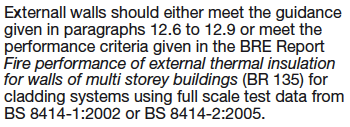
I then began to examine the guidance given by the government in Approved Document, Volume 2, at the corresponding part B4, as to how this statutory requirement can be met. Two alternative routes to compliance are given in Section 12.5:
In my last post also, I examined the provisions of paragraphs 12.6 to 12.9 and in particular of 12.6 and 12.7 which concern the fire properties of the materials used in construction. I explained that, for buildings over 18m high:
a) The requirement of 12.6 can be satisfied if the materials are UK Class 0. This classification can be achieved through satisfactory performance in two UK fire tests, BS 476 part 7 ‘Surface Spread of Flame’; and part 6 ‘Fire Propagation’. In both of these it is the surface of the board or panel that is subjected to assault by fire.
b) The requirements of 12.7 appear to apply to insulation products only. The materials must either survive trial by a furnace at 750° C, or have a calorific value of less than 3 MJ/kg. I argue that no material with a substantial component of a polymer like the PIR of the Celotex boards, or the PE of the Reynobond panels, could possibly pass these tests.
In this post I describe the BS 8414 fire test, which is offered as an alternative route to compliance at paragraph 12.5. In following posts I plan to:
i) Outline also the ‘Fire Safety engineering’ route to compliance offered in Approved Document B at paragraph 0.30.
ii) Describe the fire properties of the materials used at Grenfell tower, and thus:
iii) Establish whether the Grenfell cladding system was capable of meeting the requirements specified in any of the routes offered in the Approved Document guidelines. Then further:
iv) Examine the BCA Guidance 1 and determine whether the Grenfell system was compliant with it. [See my four part series, beginning here.]
Testing to BS 8414
As an alternative to testing the fire properties of individual components of the cladding system, BS 8414 (‘Fire performance of external cladding system’) tests the system as a whole. It comes in two versions, BS 8414-1 for cladding systems applied to a masonry face, and BS 8414-2 for systems fixed to a steel frame. It is 8414-1 that is relevant to Grenfell, with its concrete face.
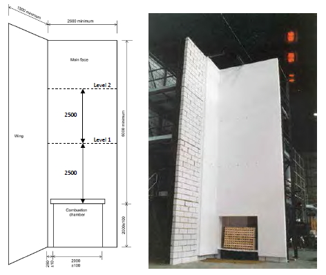
The main test wall is at least 2.6m wide and extends at least 6m above the fire source. Two levels are defined at 2.5m and 5m above the combustion chamber opening: 2
The wing wall is perpendicular to the main wall, and at least 1.5m wide. Surprisingly (to me at least), the fire source is normally a wood fire, but it is very precisely defined in terms of the type of softwood used, the size of the sticks, and the method of ignition. At its peak, the heat output is about 3MW (BS 8414-1:2015, Annex A, A.2.3):
3 MW is 3000 kW which, for those who have sat in front of a domestic electric bar fire, is comparable to a thousand 3 bar fires:
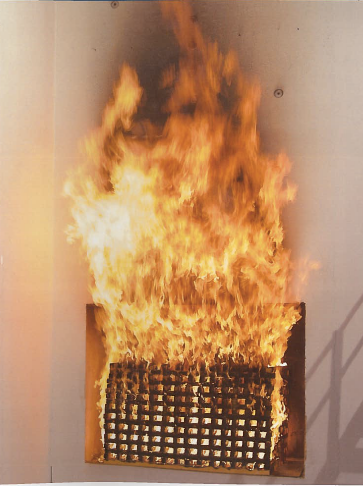
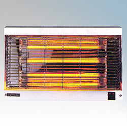 Just saying, and for me that is a salutary reminder of what brave firemen and women have to deal with. Here is a close up of the BS 8414 fire source at what looks like full output, from the cover of BRE 135, 3rd edition, ‘Fire Performance of External Thermal Insulation for Walls of Multistorey Buildings’ (BRE 2013. Sample pages):
The cladding system is attached to the wall ‘in the manner specified by the test sponsor’ (BS 8414-1:2015, 4). The test is meant to simulate conditions where an internal room fire vents through a window or other aperture:
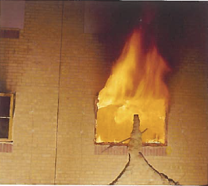
Here is BRE 135’s example of fire breaking out of a window:
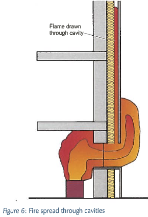
The height of the wall enables the effectiveness of the horizontal cavity barriers to be tested. In facade fires, flames within cavities can be elongated to five to ten times their original length as they ‘seek’ oxygen and fuel (BRE 135, 3.3.2). Figure 6 in BRE 135 nicely illustrates the potential danger of a system with insulation board and cladding panels and a cavity between them, if cavity barriers are absent or ineffective:
Coming back to BS 8414, the heat source is extinguished after 30 minutes, but the test can continue for up to another 30 minutes if the specimen continues to burn. It can be terminated at any time if the flame extends above the height of the test apparatus (BS 8414-1:2015, 8.6.a).
Thermocouples are placed at levels 1 and 2 both internally within layers of the cladding and externally 5cm from the cladding surface, to measure the temperature.
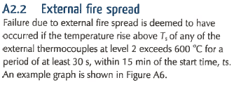
BS 8414-1 itself contains no criteria for pass and failure. As stated in Approved Document B, paragraph 12.5 above, cladding systems in England are subject to the performance criteria contained in BR 135. The system is deemed to have failed if the temperature at any of the thermocouples at level 2 reaches 600° C above ambient temperature for a period of 30 seconds or more, within 15 minutes of a carefully defined start time. Here, for example, is the failure criterion for external fire spread (BS 135, A2.2):
BS 8414-2:2005 introduced two criteria for early termination of the test:
These were not introduced formally into BS 8414-1 until the second edition of 2015, but it seems probable that procedures for the two tests would have been brought into alignment before that date, so that BS 8414-1 tests would have been terminated if flames reached above the top of the rig and of course also if there was a danger to personnel or equipment.
If a test is terminated before the crib is extinguished at 30 minutes, then no BR 135 classification can be given to the system (BR 135, 2013, p. 18):
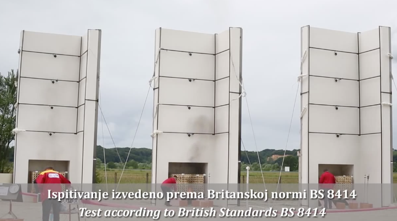
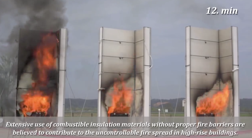
A comparative test of three cladding systems to BS 8414 was carried out in May 2014 in Croatia in the open air before a grandstand audience equipped with face masks. It has been described in a scientific paper 3 and in a lecture in the Faculty of Engineering at the University of Zagreb, which contained footage from the test:
System 1 on the left had combustible expanded polystyrene EPS insulation (EN 13501-1 Class B) without cavity barriers; System 2 in the middle had EPS insulation with a 20cm horizontal stone wool fire barrier; and System 3 on the right had stone wool insulation (EN 13501-1 Class A2). At 12 minutes after ignition, System 1’s flame has reached the top of the wall:
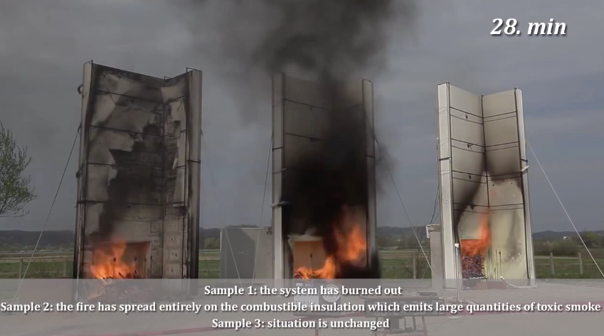
At 28 minutes, System 1 has burned out; System 2 is emitting large quantities of toxic smoke from combustion of the insulation; and System 3 is successfully resisting the fire:
The average temperatures within the thermal insulation layer at level 2 tell the story: 4
The ambient temperature seems to have been about 15-20° C. The temperature in System 1 rose above 615-20° C in both the main face and the wing for about 2 minutes. This system would therefore have failed under the BS 135 criterion. Temperatures in System 2 rose to only around 100-200° C, while the temperature in System 3 rose by only around 5-10° C.
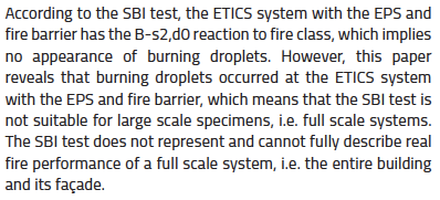
In passing, it is worth mentioning that in System 2, flaming droplets fell from the EPS as it melted. Bjegović points out in her paper (p. 368) that these EPS boards had achieved a d0 class for droplets under EN 13501-1, meaning that no flaming droplets were observed when the boards were tested under EN 13823 (also known as the Small Burning Object or SBI test). In the following quotation ETICS stands for External Insulation Composite Systems:
This comparative test in Croatia demonstrates the usefulness of the BS 8414 test. I must admit I am slightly concerned by how narrowly System 1 failed to meet the BR 135 criterion. Could there be another cladding system which would also spread the fire rapidly upwards in this test, but whose temperature would not quite reach 600° C above ambient for the required 30 seconds, with the result that it could be deemed by someone to have ‘passed’ the test, despite being completely burned out in a short time? I do have a great deal of confidence in the experts at BRE and trust that they chose this criterion with care and caution, but nevertheless it seems to me to be a question at least worth asking.
Andrew Chapman
(continued in part 3)
Postscript, 1 March 2018
The results of the DCLG tests of 23 July to 16 August:
demonstrate that the BS 8414 tests are not without bite. In the test of the Grenfell-type system with PE ACM and PIR insulation, the BR 135 failure criterion was reached after just 6 minutes. The two tests with Fire Retardant ACM and plastic insulation were terminated before 30 minutes because of flame spread above the rig, preventing them from receiving a BR 135 classficiation, and were thus counted as failures.
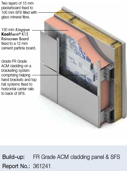
The failure of DCLG Test 7 (FR + Phenolic) must have been of particular concern to Kingspan who had installed systems of this type on the basis of Desktop Studies. Here is one such system, from a 2016 Kingspan brochure:
and Chris Cook of Newsnight has reported on the approval by Exova Warringtonfire through Desktop Studies of two systems with Kingspan K15 and Fire Retardant ACM.
On 9 October 2017, a similar system with Kingspan K15 insulation boards and Alpolic FR ACM panels was tested at the BRE (Test Report, Classification Report). It passed the test, but by a small margin. After 26 minutes flames reached to the top of the highest panels:
and thus virtually to the top of the rig. A little higher, and the test would have been terminated.
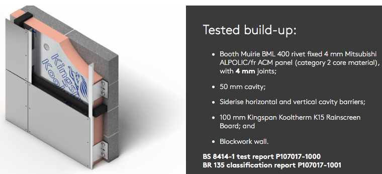
How was this pass achieved, after the failure of DCLG Test 7? Kingspan describe the tested build-up as follows, highlighting the remarkably narrow 4 mm gap between the panels:
Nick Jenkins of Booth Muirie Ltd, a company wholly owned (p. 133) by Kingspan, commented that this test, along with a second test, showed the ‘critical effect’ that panel joint size has on fire performance:
The Test Report confirms that a 4 mm gap was left between the panels:
and the Classification Report specifies that the classification achieved applies only to systems with a 4 mm panel gap:
Remarkably, the BRE specify no tolerance for the panel gap size. In the absence of a specified tolerance, I think the requirement must be that the gap should be 4 mm ± 0.5 mm, that is to say that it must be closer to 4 mm than to 3 mm or 5 mm. Is this achievable in practice?
The nominal panel gap for all the DCLG test systems was 20 mm. After installation the actual panel gap was measured. For Test 7, the measured gaps varied between 17 mm and 27 mm:
The full size panels were nearly a metre wide and 2.3 metres high:
It is hardly surprising that the gap between such panels varied by 10 millimetres. If this was the best that could be achieved in the relative comfort of an indoor burn hall, with little or no limitation on time, what tolerance would be realistic on a building site, with less specialised workers, wind, and constraints on time? Not half a millimetre, I think all must agree.
Why are Kingspan testing their combustible insulation product with combustible FR ACM at all, after the failure of DCLG test 7? It should be obvious that this is a dangerous combination. And why did the BRE make their test facility available for these tests? Dr Peter Bonfield, Chief Executive of the BRE, sits on the Expert Panel appointed by the Government to advise it on how
to make buildings safe
following the Grenfell fire. On 5 September 2017, based on this Expert Panel’s advice, the DCLG advised building owners that systems with rigid polymeric foam (including phenolic foam) insulation in combination with FR ACM panels present (p. 6)
a notable fire hazard
on buildings over 18 metres:
There is of course nothing wrong in principle with conducting experiments to investigate the effect of panel gap size on fire performance. But is this a realistic approach, given the exigencies of real life construction? Was not 20 mm chosen for the DCLG tests because that allows for a tolerance that can be achieved on site?
And if this is to be viewed as a sincere investigation into the effect of panel gap size, why did the BRE not provide a record of the actual measured gaps attained in the installed system, as they did with the DCLG tests?
And why did the BRE issue a BR 135 Classification for a system that could not be built, since it is defined as having 4 mm panel gaps, which cannot possibly be attained on site to ± 0.5 mm tolerance? What sort of sense does this make?
Andrew Chapman
